
Product Description
Roll bar joints steering yokes uprights stop joint yokes
Our Advantages
1,We have advanced forging equipments, including ring rolling machines, 1000T hydraulic presses, 750kg forging hammers, 1T air hammers, 2T, 3T, 10T hydraulic forging hammers, etc. It can produce various types of forgings from 10kg to 10 tons. Whether it is free forging or simple die forging products, the company can meet the requirements for forgings of various shapes.
2,In addition, we are also equipped with several heat treatment furnaces (equipment) to ensure that forgings meet their performance requirements after heat treatment.
3, In order to ensure product quality, the company has a well-equipped laboratory that can conduct precise laboratory analysis of raw materials and mechanical properties.
4,At the same time, the company also introduced high-precision processing equipment such as CNC lathes, machining centers, deep hole processing equipment, and milling machines to achieve full independent production from forgings to finished products.
5,It is worth mentioning that our entire production process is controlled independently and there is no outsourced processing. This means that every step from raw material procurement, forging processing, heat treatment to finished product delivery is strictly controlled by us.
6,Through refined management and cost control, we are able to provide customers with more competitive prices while ensuring product quality.
Product Description
1, Raw material: use ESR ingot. ESR need to melt twice, secondary refining process.Non metallic inclusions in steel are absorbed by slag.
2, Heat – Natural gas heating furnaces are monitored and controlled by computer programs to ensure precise heating within set time and temperature range as required.
3, Forging
4, Normalized:can improve the toughness of steel
5, Aligning
6, Pre-machining
7, Make UT (ultrasonic) inspection
8, Heat treatment: Quenching&Tempering, to meet mechanical performance requirements.
9, Deep hole drilling
10, Precision machining, to achieve dimenssion on drawings.
The materials we can forging
| Stainless Steel: | SS201,SS301, SS303, SS304, SS316, SS316L,SS416 ,AISI 440C,17-4PH etc. |
| Steel/Alloy: | mild steel, Carbon steel, 4140, 4340,65Mn,60Si2Mn, Q235, Q345B, 1571steel, 1045steel,A106,A105, A570-50,CR-MO4130,Astm A487 grade 9A, 52100 Bearing steel ,S45c, Sm490A, AVP/S235JRG2,DD14, 1.0037 ,etc, ASTM 1197-47, 25CRMO4V,SCM435, 11SMNPB30,1. 0571 ,.A36 |
| Brass: | HPb63, HPb62, HPb61, HPb59, H59, H62, H68, H80 ,Bronze 660, C93200,Bronze CDA873 or 956,CDA873,C95600,MAILEABLE IRON ASTM A47-77, etc. |
| Copper: | C11000,C12000,C12000 C36000,C100 etc. |
| Aluminum: | AL1100,AL6061, Al6063-T6, AL6082, AL7075, AL5052, A380 etc. |
| Titanium: | CP Ti,Ti-6Al-4V, Ti-6Al-4V Eli,Ti-3Al-2.5V,Ti-5Al-2.5Sn, Ti-5Al-2.5Sn Eli,Ti-0.05Pd, Ti-0.2Pd, Ti-6Al-7Nb,Ti-13Nb-13Zr,Ti-0.1Ru,Ti-3Al-8V-6Cr-4Mo-4Zr,Ti-6Al-4V-0.1Ru,Etc. |
| The Surface Treatment: | Zinc plating, Chrome plating, Nickel plating, Tin plating, Polishing, Anodizing, Power-coating, Dacromet, Oxide black, Sandblast Anodizing, Electroless nickel, Fe/Zn8/C PER ISO 2081, etc. |
Detailed Photos
/* January 22, 2571 19:08:37 */!function(){function s(e,r){var a,o={};try{e&&e.split(“,”).forEach(function(e,t){e&&(a=e.match(/(.*?):(.*)$/))&&1
| Processing Object: | Metal |
|---|---|
| Molding Style: | Forging |
| Molding Technics: | Pressure Casting |
| Application: | Machinery Parts |
| Material: | Steel |
| Heat Treatment: | Quenching |
| Samples: |
US$ 1/Piece
1 Piece(Min.Order) | |
|---|
| Customization: |
Available
| Customized Request |
|---|

What is the lifespan of a typical bevel gear?
The lifespan of a typical bevel gear can vary depending on several factors, including the quality of the gear, the operating conditions, maintenance practices, and the specific application. Here’s a detailed explanation:
Bevel gears, like any mechanical component, have a finite lifespan. The lifespan of a bevel gear is influenced by the following factors:
- Quality of the Gear: The quality of the gear itself is a significant factor in determining its lifespan. Bevel gears manufactured using high-quality materials and precise manufacturing processes tend to have longer lifespans. Gears made from durable materials and manufactured with tight tolerances and accurate tooth profiles are more resistant to wear and fatigue, resulting in extended lifespans.
- Operating Conditions: The operating conditions under which the bevel gear operates greatly affect its lifespan. Factors such as torque levels, rotational speed, temperature, and shock loads can impact the wear and fatigue characteristics of the gear. Gears subjected to high torque, high-speed rotation, excessive heat, or frequent heavy loads may experience accelerated wear and reduced lifespan compared to gears operating under milder conditions.
- Maintenance Practices: Proper maintenance practices can significantly extend the lifespan of a bevel gear. Regular inspection, lubrication, and preventive maintenance help identify and address potential issues before they escalate. Adequate lubrication, cleanliness, and alignment contribute to reducing wear, minimizing the risk of damage, and prolonging the gear’s lifespan. Neglecting maintenance or improper maintenance practices can lead to premature wear, failure, and reduced lifespan.
- Application Specifics: The specific application in which the bevel gear is used plays a vital role in determining its lifespan. Different applications impose varying loads, speeds, and operating conditions on the gear. Gears used in heavy-duty industrial applications, such as mining or heavy machinery, may experience more significant wear and have shorter lifespans compared to gears used in lighter-duty applications.
- Load Distribution: Proper load distribution among the gear teeth is critical for ensuring longevity. Evenly distributed loads help prevent localized wear and ensure that no individual teeth are subjected to excessive stress. Factors such as gear design, tooth profile, and accurate alignment influence load distribution and can impact the gear’s lifespan.
Due to the complex interplay of these factors, it is challenging to provide a specific lifespan for a typical bevel gear. However, with proper design, high-quality manufacturing, suitable operating conditions, regular maintenance, and appropriate load distribution, bevel gears can have a lifespan ranging from several thousand to tens of thousands of operating hours.
It is important to note that monitoring the gear’s condition, including wear patterns, tooth damage, and any signs of failure, is crucial for ensuring safe and reliable operation. When signs of wear or damage become significant or when the gear no longer meets the required performance criteria, replacement or refurbishment should be considered to maintain the overall system’s integrity and performance.
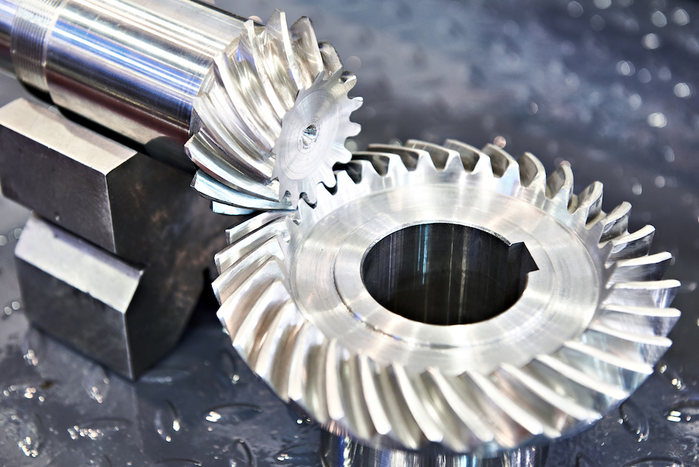
How do you calculate the efficiency of a bevel gear?
To calculate the efficiency of a bevel gear, you need to compare the power input to the gear with the power output and account for any losses in the gear system. Here’s a detailed explanation of the calculation process:
The efficiency of a bevel gear can be calculated using the following formula:
Efficiency = (Power output / Power input) x 100%
Here’s a step-by-step breakdown of the calculation:
- Calculate the Power Input: Determine the power input to the bevel gear system. This can be obtained by multiplying the input torque (Tin) by the input angular velocity (ωin), using the formula:
- Calculate the Power Output: Determine the power output from the bevel gear system. This can be obtained by multiplying the output torque (Tout) by the output angular velocity (ωout), using the formula:
- Calculate the Efficiency: Divide the power output by the power input and multiply by 100% to obtain the efficiency:
Power input = Tin x ωin
Power output = Tout x ωout
Efficiency = (Power output / Power input) x 100%
The efficiency of a bevel gear represents the percentage of input power that is effectively transmitted to the output, considering losses due to factors such as friction, gear meshing, and lubrication. It is important to note that the efficiency of a bevel gear system can vary depending on various factors, including gear quality, alignment, lubrication condition, and operating conditions.
When calculating the efficiency, it is crucial to use consistent units for torque and angular velocity. Additionally, it’s important to ensure that the power input and output are measured at the same point in the gear system, typically at the input and output shafts.
Keep in mind that the calculated efficiency is an approximation and may not account for all the losses in the gear system. Factors such as bearing losses, windage losses, and other system-specific losses are not included in this basic efficiency calculation. Actual efficiency can vary based on the specific design and operating conditions of the bevel gear system.
By calculating the efficiency, engineers can evaluate the performance of a bevel gear and make informed decisions regarding gear selection, optimization, and system design.
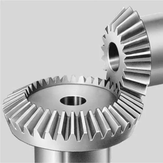
How do you calculate the gear ratio of a bevel gear?
Calculating the gear ratio of a bevel gear involves determining the ratio between the number of teeth on the driving gear (pinion) and the driven gear (crown gear). Here’s a detailed explanation of how to calculate the gear ratio of a bevel gear:
The gear ratio is determined by the relationship between the number of teeth on the pinion and the crown gear. The gear ratio is defined as the ratio of the number of teeth on the driven gear (crown gear) to the number of teeth on the driving gear (pinion). It can be calculated using the following formula:
Gear Ratio = Number of Teeth on Crown Gear / Number of Teeth on Pinion Gear
For example, let’s consider a bevel gear system with a crown gear that has 40 teeth and a pinion gear with 10 teeth. The gear ratio can be calculated as follows:
Gear Ratio = 40 / 10 = 4
In this example, the gear ratio is 4:1, which means that for every four revolutions of the driving gear (pinion), the driven gear (crown gear) completes one revolution.
It’s important to note that the gear ratio can also be expressed as a decimal or a percentage. For the example above, the gear ratio can be expressed as 4 or 400%.
Calculating the gear ratio is essential for understanding the speed relationship and torque transmission between the driving and driven gears in a bevel gear system. The gear ratio determines the relative rotational speed and torque amplification or reduction between the gears.
It’s worth mentioning that the gear ratio calculation assumes ideal geometries and does not consider factors such as backlash, efficiency losses, or any other system-specific considerations. In practical applications, it’s advisable to consider these factors and consult gear manufacturers or engineers for more accurate calculations and gear selection.
In summary, the gear ratio of a bevel gear is determined by dividing the number of teeth on the crown gear by the number of teeth on the pinion gear. The gear ratio defines the speed and torque relationship between the driving and driven gears in a bevel gear system.


editor by Dream 2024-05-15
 English
  Italian