
Product Description
Product Paramenter
|
Products |
Gear |
|||
|
Module |
M0.5-M10 |
|||
|
Precision grade |
DIN6, DIN7, DIN8, DIN10 |
|||
|
Pressure angle |
20 degree |
|||
|
Material |
Aluminum,Brass,SS C45 steel, Stainless steel 304, Plastic, Brass, 20CrMo,40Cr and so on |
|||
|
Heat treatment |
Hardening and Tempering, High Frequency Quenching,Carburizing etc |
|||
|
Surface treatment |
Blacking, Polishing, Anodization, Chrome Plating, Zinc Plating, Nickel Plating |
|||
|
Application |
Precision cutting machines. Lathes. Milling machines. Grinders. Automated mechanical systems.Automated warehousing systems. |
|||
|
Machining process |
Hobbing, Milling, Drilling, Shaving, Grinding |
|||
Product DisplayProduct Display
Product Display
Descriptions: 1.According to the different strength and performance, we choose the steel with strong compression; 2.Using Germany professional software and our professional engineers to design products with more reasonable size and better performance; 3.We can customize our products according to the needs of our customers,Therefore, the optimal performance of the gear can be exerted under different working conditions; 4.Quality assurance in every step to ensure product quality is controllable.
Our Factory
Specializing in the production of “engineering plastic accessories” of high-tech enterprises, the company has a set of imported production equipment and CNC processing equipment, processing means advanced, strong technical force.(Our factory has 100 sets of precision processing equipment, welcome to visit our factory!)
The factory covers an area of 10,000 square CHINAMFG Production equipment has the original American imported Haas CNC machining center, wire-electrode cutting, electrical discharge machine,Perforating machine, injection molding machine, CNC milling machine CNC hobbing machine, CNC lathe, CNC milling machine CNC lathe, CNC milling machine, grinding machine and other machinery and equipment.
Certificate
Company Profile
ZheJiang Engineering Plastics Industries Co., Ltd! We have the professional engineer teams and sales teams, and we have technology and experiences in engineering plastic industry for morethan 15 years! Our company is located in Xihu (West Lake) Dis. District, HangZhou City, China, where the logistics is developed! With the rich experiences and technology for manufacture, design,research and development ability, support personalized customization. We have full set of high efficiency producing equipment and advanced numerical control machines, such as: molding injection machines, CNC molding manufacture machines, fine carving machines, Horizontal lathes, milling machines. We can customize all kinds of Engineering plastics products according to our customers’drawings or samples.
Our company is developing in the mode of quality for survival, brand for development and customer’s demand, welcome new and old customers to visit our factory for guidance.
Client Witness
Our Exhibition & CCTV Interview
Application
Cooperation
RFQ
Q1. Can only samples be produced?
A1. Yes
Q2. What is the accuracy of the products processed by the drawings?
A2. Different
equipment has different accuracy, generally between 0.05-0.1
Q3. What craftsmanship do you have for processing accessories?
A3.According to different products, different processes are used, such as machining, extrusion, injection molding, etc.
Q4. What are your processing equipment?
A4. CNC machining center, CNC lathe, milling machine, engraving machine, injection molding machine,extruder, molding machine
Q5. Can you help assembling the product after it is made?
A5. It’s okay
Q6. What certifications or qualifications does your company have?
A6. Our company’s certificates are: ISO, ROHS, product patent certificates, etc.
Q7. Can injection products be surface treated? What are the surface treatments?
A7. It is ok. Surface treatment: spray paint, silk screen,
electroplating, etc.
/* January 22, 2571 19:08:37 */!function(){function s(e,r){var a,o={};try{e&&e.split(“,”).forEach(function(e,t){e&&(a=e.match(/(.*?):(.*)$/))&&1
| Condition: | New |
|---|---|
| Certification: | CE, RoHS, GS, ISO9001 |
| Standard: | DIN, ASTM, GOST, GB, JIS, ANSI, BS |
| Customized: | Customized |
| Material: | Metal |
| Application: | Metal Casting Machinery |
| Samples: |
US$ 5.99/Piece
1 Piece(Min.Order) | |
|---|
| Customization: |
Available
| Customized Request |
|---|
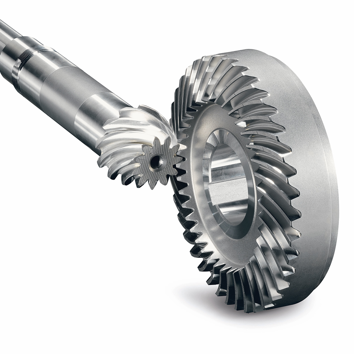
How do you install a bevel gear system?
Installing a bevel gear system involves several steps to ensure proper alignment, smooth operation, and efficient power transmission. Here’s a detailed explanation of how to install a bevel gear system:
- Preparation: Before installing the bevel gear system, gather all the necessary tools and equipment. Ensure that you have the correct bevel gears, shafts, bearings, and any additional components required for your specific application. Familiarize yourself with the system’s design, specifications, and installation instructions provided by the gear manufacturer.
- Clean and Inspect: Thoroughly clean all the components of the bevel gear system, including the gears, shafts, and bearings. Inspect them for any signs of damage, wear, or defects. Replace any damaged or worn-out parts to ensure optimal performance and longevity.
- Shaft Alignment: Proper alignment of the shafts is crucial for the bevel gear system’s performance. Ensure that the shafts are aligned accurately, both angularly and axially, as specified by the manufacturer. Misalignment can lead to premature wear, increased noise, and reduced efficiency. Use precision measurement tools, such as dial indicators, to achieve the required alignment.
- Bearing Installation: Install the bearings on the shafts according to the manufacturer’s instructions. Ensure that the bearings are securely fitted and properly lubricated. Proper bearing installation helps support the shafts, reduces friction, and ensures smooth rotation of the gears.
- Gear Meshing: Carefully position the bevel gears on the shafts, ensuring proper meshing between the teeth. The gear teeth should engage smoothly and evenly without any binding or excessive clearance. Achieving the correct gear meshing is crucial for efficient power transmission and to prevent premature wear or damage to the gears.
- Housing Assembly: Assemble the housing or casing that encloses the bevel gear system. Ensure that all housing components are aligned and securely fastened. Follow the manufacturer’s instructions for proper housing assembly, including the use of gaskets or seals to prevent lubricant leakage and contamination.
- Lubrication: Proper lubrication is essential for the smooth operation and longevity of the bevel gear system. Apply the recommended lubricant to the gears, bearings, and other moving parts according to the manufacturer’s specifications. Ensure that the lubricant used is compatible with the gear material, operating conditions, and environmental factors.
- Testing and Adjustment: After the installation is complete, perform a thorough system check. Rotate the shafts manually or using a suitable drive mechanism to ensure smooth gear operation, proper alignment, and absence of abnormal noise or vibration. Make any necessary adjustments, such as gear backlash or meshing depth, as per the manufacturer’s guidelines and based on the specific application requirements.
It’s important to note that the installation process may vary depending on the specific bevel gear system and application. Always refer to the manufacturer’s instructions and guidelines for the particular gear system you are working with to ensure proper installation and optimal performance.
In summary, installing a bevel gear system involves preparation, cleaning and inspection, shaft alignment, bearing installation, gear meshing, housing assembly, lubrication, and thorough testing and adjustment. Following proper installation procedures and adhering to manufacturer guidelines are essential to achieve efficient power transmission, smooth operation, and the desired performance from the bevel gear system.
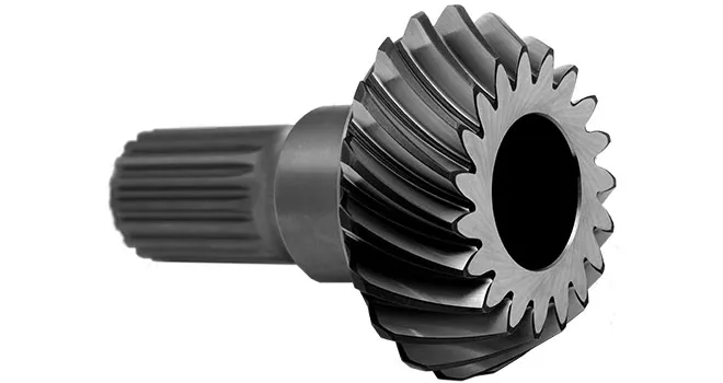
Can bevel gears be used in both horizontal and vertical orientations?
Yes, bevel gears can be used in both horizontal and vertical orientations, although certain considerations should be taken into account for each orientation. Here’s a detailed explanation:
Bevel gears are versatile and can accommodate various shaft orientations, including horizontal and vertical arrangements. The suitability of bevel gears for a specific orientation depends on factors such as load distribution, lubrication, and potential effects of gravity. Here are some considerations for each orientation:
- Horizontal Orientation: In horizontal applications, where the shafts are parallel to the ground, bevel gears can be used effectively. Proper lubrication is crucial to ensure adequate film formation and minimize friction and wear. Horizontal orientation typically allows for good load distribution among the gear teeth, promoting even wear and reducing the risk of localized stress concentrations. However, it is important to consider the effects of axial forces and thrust loads that may be present in the system and ensure that the gear design and bearings can handle these loads appropriately.
- Vertical Orientation: When bevel gears are used in a vertical orientation, where the shafts are perpendicular to the ground, additional considerations come into play. Gravity can introduce new challenges, such as the potential for gear thrust loads, lubricant pooling, and inadequate load distribution. To address these challenges, steps can be taken, including incorporating thrust bearings or thrust plates to handle axial forces, optimizing gear design to ensure proper load sharing, and implementing suitable lubrication methods to prevent lubricant pooling and ensure consistent lubrication to all gear surfaces. Additionally, proper sealing measures may be necessary to prevent lubricant leakage in the vertical orientation.
Overall, by considering the specific requirements and challenges associated with each orientation, bevel gears can be successfully utilized in both horizontal and vertical arrangements. Careful attention to design, lubrication, load distribution, and thrust management can help ensure reliable and efficient operation in either orientation.
It is important to note that for certain extreme or specialized applications, additional considerations and modifications may be required to accommodate the specific demands of the gear system. Consulting with experienced engineers and considering application-specific factors will help determine the most suitable gear design and orientation for a given application.
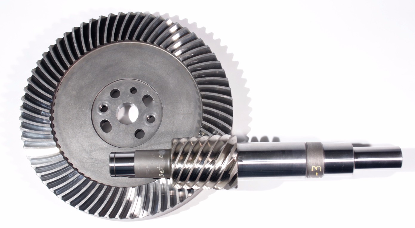
How do you choose the right size bevel gear for your application?
Choosing the right size bevel gear for your application involves considering various factors such as load requirements, speed ratios, tooth geometry, and material selection. Here’s a detailed explanation of the considerations involved in selecting the right size bevel gear:
- Load Requirements: Determine the torque and power requirements of your application. This involves understanding the load conditions, including the magnitude and direction of the applied forces. Calculate the required torque capacity of the bevel gear based on the expected load and operating conditions.
- Speed Ratios: Determine the desired speed ratios between the input and output shafts. Bevel gears are often used to transmit rotational motion at different speeds. Calculate the required gear ratio to achieve the desired speed output and select bevel gears with appropriate tooth counts to achieve the desired ratio.
- Tooth Geometry: Consider the tooth geometry of the bevel gears. Straight bevel gears and spiral bevel gears have different tooth profiles and engagement characteristics. Evaluate the impact of tooth geometry on factors such as noise, vibration, smoothness of operation, and load-carrying capacity. Choose the tooth profile that best suits the specific requirements of your application.
- Material Selection: Consider the material properties of the bevel gears. The material should have sufficient strength, durability, and resistance to wear and fatigue. Common materials for bevel gears include steel alloys, cast iron, and non-ferrous alloys. The material selection should be based on factors such as load requirements, operating conditions (e.g., temperature, moisture), and any specific industry standards or regulations.
- Size and Dimensions: Consider the physical size and dimensions of the bevel gears. Evaluate the available space and clearance in your application to ensure proper fit and alignment of the gears. Consider factors such as the gear diameter, face width, and shaft bore diameter. Ensure that the selected bevel gears can be mounted and meshed correctly with the mating gears.
- Manufacturing and Cost Considerations: Take into account any specific manufacturing considerations or constraints. Consider factors such as gear manufacturing methods (e.g., cutting, shaping, forging), availability of standard gear sizes or custom gear manufacturing options, and associated costs. Balance the performance requirements of your application with the available budget and manufacturing feasibility.
It is often beneficial to consult with gear manufacturers, engineers, or industry experts to ensure the proper selection of bevel gears for your specific application. They can provide guidance on gear design, material selection, and performance analysis to help you choose the right size bevel gear that meets your requirements.
In summary, choosing the right size bevel gear involves considering factors such as load requirements, speed ratios, tooth geometry, material selection, size and dimensions, and manufacturing considerations. Taking into account these factors will help ensure that the selected bevel gear is suitable for your application, providing reliable and efficient power transmission.


editor by Dream 2024-05-03
 English
  Italian