
Descrizione del prodotto
SUS303 304 Steel 40Cr 20CrMoTi SCM415 Spur Bevel Gear
Gear transmission relies on the thrust between gear teeth to transmit motion and power, also known as meshing transmission. With this gradual meshing, helical gears operate much more smoothly and quietly than spur gears. Therefore, almost all automobile transmissions use helical gears.Since the teeth on the helical gear present a certain angle, the gears will be under a certain amount of stress when they mesh. Equipment using helical gears is equipped with bearings to withstand this pressure.
Descrizione del prodotto
| Product name | Spur Gear & Helical Gear & Gear Shaft |
| Customized service | OEM, drawings or samples customize |
| Materials Available | Stainless Steel, Carbon Steel, S45C, SCM415, 20CrMoTi, 40Cr, Brass, SUS303/304, Bronze, Iron, Aluminum Alloy etc |
| Heat Treatment | Quenching & Tempering, Carburizing & Quenching, High-frequency Hardening, Carbonitriding…… |
| Surface Treatment | Conditioning, Carburizing and Quenching,Tempering ,High frequency quenching, Tempering, Blackening, QPQ, Cr-plating, Zn-plating, Ni-plating, Electroplate, Passivation, Picking, Plolishing, Lon-plating, Chemical vapor deposition(CVD), Physical vapour deposition(PVD)… |
| BORE | Finished bore, Pilot Bore, Special request |
| Processing Method | Molding, Shaving, Hobbing, Drilling, Tapping, Reaming, Manual Chamfering, Grinding etc |
| Pressure Angle | 20 Degree |
| Hardness | 55- 60HRC |
| Size | Customer Drawings & ISO standard |
| Package | Wooden Case/Container and pallet, or made-to-order |
| Certificate | ISO9001:2008 |
| Machining Process | Gear Hobbing, Gear Milling, Gear Shaping, Gear Broaching, Gear Shaving, Gear Grinding and Gear Lapping |
| Applications | Printing Equipment Industry, Laser Equipment Industry, Automated Assemblyline Industry, Woodening Industry, Packaging Equipment Industry, Logistics storage Machinery Industry, Robot Industry, Machine Tool Equipment Industry |
Company Profile
Packaging & Shipping
FAQ
| Main Markets? | North America, South America, Eastern Europe , West Europe , Southeast ASIA and so on |
| How to order? | 1, You send us drawing or sample |
| 2,We check it and project assessment | |
| 3,We Quote you price or give you our design for your confirmation | |
| 4, We make the sample for your confirmation | |
| 5, you place the formal an order and pay us down payment for production after confirmation | |
| 6, We start producing and fix the production time. | |
| 7, When our goods is done, we notice you the shippment time ,and request you arrange the balance , will track the transportation matter | |
| 8, following the usage services and long-term cooperation. |
If you are interested in our products, please send me your specification Drawing. /* January 22, 2571 19:08:37 */!function(){function s(e,r){var a,o={};try{e&&e.split(“,”).forEach(function(e,t){e&&(a=e.match(/(.*?):(.*)$/))&&1
| Applicazione: | Electric Cars, Motorcycle, Machinery, Agricultural Machinery, Automation Equipment |
|---|---|
| Hardness: | Hardened Tooth Surface |
| Gear Position: | External Gear |
| Manufacturing Method: | Rolling Gear |
| Forma della porzione dentata: | Bevel Wheel |
| Materiale: | Carbon Steel |
| Samples: |
US$ 15/Piece
1 Piece(Min.Order) | |
|---|
| Customization: |
Available
| Customized Request |
|---|
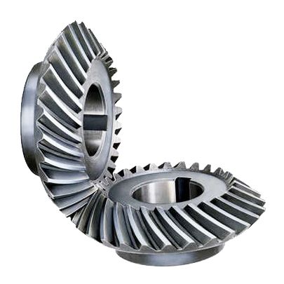
Can bevel gears be used in precision manufacturing equipment?
Yes, bevel gears can be used in precision manufacturing equipment due to their ability to transmit motion and power at varied angles with high accuracy. Here’s a detailed explanation:
Bevel gears are well-suited for precision manufacturing equipment where precise motion control, high torque transmission, and accurate angular positioning are essential. Here are some key reasons why bevel gears are suitable for such applications:
- Angular Transmission: Bevel gears excel at transmitting motion and power between intersecting shafts at different angles. In precision manufacturing equipment, where components often require precise angular positioning, bevel gears provide an efficient means of achieving the necessary motion transfer. They allow for smooth and accurate rotation, ensuring precise alignment and positioning of machine components.
- Compact Design: Bevel gears have a compact design, making them suitable for applications where space is limited. In precision manufacturing equipment, where machines often have complex structures and require tight integration of components, the compact size of bevel gears allows for efficient utilization of available space. This is particularly advantageous when designing compact and high-precision machinery.
- High Torque Transmission: Bevel gears are capable of transmitting high torque loads, making them suitable for precision manufacturing equipment that requires the transmission of substantial power. Whether it’s in rotary tables, indexing mechanisms, or gearboxes, bevel gears can efficiently transfer high torque while maintaining accuracy and precision in motion control.
- Accuracy and Backlash Control: In precision manufacturing equipment, minimizing backlash and ensuring accurate motion control are critical. Bevel gears can be manufactured with high precision to achieve tight tolerances and minimal backlash. This allows for precise positioning, accurate motion control, and repeatable performance, which are essential in precision manufacturing processes.
- Customization Options: Bevel gears can be customized to meet specific requirements of precision manufacturing equipment. Different tooth profiles, gear ratios, materials, and surface treatments can be employed to optimize the gear performance for specific applications. This customization capability allows gear engineers to design bevel gears that precisely match the needs and specifications of the equipment.
Examples of precision manufacturing equipment where bevel gears are commonly used include CNC machines, milling machines, gear hobbing machines, rotary tables, indexing mechanisms, and various types of gearboxes. These machines rely on the precise and reliable motion transmission provided by bevel gears to achieve accurate and high-quality manufacturing processes.
It is important to note that the selection and design of bevel gears for precision manufacturing equipment should consider factors such as load requirements, speed, operating conditions, backlash limitations, and noise considerations. Gear engineers and machine designers often conduct detailed analyses and calculations to ensure the bevel gears meet the necessary performance criteria and contribute to the overall precision and reliability of the equipment.
In summary, bevel gears are well-suited for precision manufacturing equipment due to their ability to provide accurate angular transmission, compact design, high torque transmission, and customization options. Incorporating bevel gears in precision machinery contributes to precise motion control, accurate positioning, and reliable performance, enabling the production of high-quality and precise manufactured components.
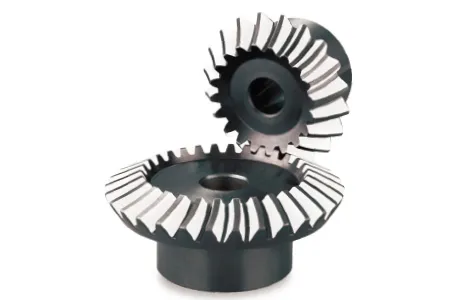
Come si assicura il corretto allineamento quando si collega una coppia conica?
Un allineamento corretto è fondamentale quando si collega un ingranaggio conico per garantire una trasmissione efficiente della potenza, un funzionamento regolare e una lunga durata del sistema di ingranaggi. Ecco una spiegazione dettagliata di come garantire un allineamento corretto:
Quando si collega un ingranaggio conico, le seguenti operazioni possono contribuire a garantire un allineamento corretto:
- Controllare le specifiche dell'ingranaggio: Per prima cosa, esaminare le specifiche dell'ingranaggio fornite dal produttore. Queste includono informazioni sul progetto dell'ingranaggio, sulle tolleranze e sui requisiti di allineamento. La comprensione di queste specifiche è essenziale per ottenere l'allineamento desiderato.
- Preparare le superfici di montaggio: Assicurarsi che le superfici di montaggio degli ingranaggi, come gli alberi o i riduttori, siano pulite, prive di detriti e adeguatamente preparate. Eventuali irregolarità o difetti superficiali possono influire sull'allineamento e causare problemi di disallineamento. Rimuovere eventuali bave, intaccature o punti ruvidi che potrebbero interferire con il corretto alloggiamento degli ingranaggi.
- Utilizzare gli strumenti di allineamento: Gli strumenti di allineamento, come gli indicatori a quadrante o i sistemi di allineamento laser, possono essere utili per ottenere un allineamento preciso. Questi strumenti consentono di misurare e regolare con precisione la posizione dell'ingranaggio rispetto ai componenti di accoppiamento. Seguire le istruzioni fornite con gli strumenti di allineamento per impostare ed eseguire correttamente il processo di allineamento.
- Allineamento assiale: Il corretto allineamento assiale è fondamentale per le ruote coniche. L'allineamento assiale si riferisce all'allineamento dell'asse di rotazione dell'ingranaggio parallelo all'asse di rotazione dell'ingranaggio di accoppiamento. Ciò garantisce un corretto ingranamento e una corretta distribuzione del carico. Utilizzare gli strumenti di allineamento per misurare e regolare l'allineamento assiale, apportando le necessarie modifiche alla posizione dell'ingranaggio o spessorando come richiesto.
- Allineamento radiale: L'allineamento radiale prevede l'allineamento dell'asse di rotazione dell'ingranaggio perpendicolare all'asse di rotazione dell'ingranaggio di accoppiamento. Un corretto allineamento radiale aiuta a prevenire i carichi laterali, l'usura eccessiva e la generazione di rumore. Utilizzare gli strumenti di allineamento per misurare e regolare l'allineamento radiale, assicurandosi che la posizione dell'ingranaggio sia regolata o spessorata correttamente per ottenere l'allineamento desiderato.
- Verificare lo schema di contatto dei denti: Dopo aver allineato gli ingranaggi, è importante verificare l'andamento del contatto dei denti. Lo schema di contatto dei denti deve essere uniformemente distribuito sulle superfici dei denti dell'ingranaggio per garantire una corretta ripartizione del carico e ridurre al minimo l'usura. Eseguire un'ispezione visiva o utilizzare strumenti specializzati, come i composti per la marcatura degli ingranaggi, per controllare e regolare lo schema di contatto dei denti, se necessario.
Seguendo questi passaggi e utilizzando gli strumenti di allineamento appropriati, è possibile garantire un allineamento corretto quando si collega una coppia conica. Un allineamento corretto favorisce una trasmissione efficiente della potenza, minimizza l'usura, riduce la rumorosità e prolunga la durata del sistema di ingranaggi.
Vale la pena di notare che ogni sistema di ingranaggi può avere requisiti e considerazioni specifiche per l'allineamento. Consultare le linee guida e le best practice del produttore di ingranaggi e rivolgersi a ingegneri esperti per garantire il corretto allineamento degli ingranaggi conici nella propria applicazione specifica.
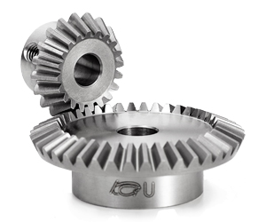
How do bevel gears differ from other types of gears?
Bevel gears have distinct characteristics that set them apart from other types of gears. Here’s a detailed explanation of how bevel gears differ from other gears:
1. Tooth Geometry: Bevel gears have teeth cut on the cone-shaped surface of the gears, whereas other types of gears, such as spur gears and helical gears, have teeth cut on cylindrical surfaces. The tooth geometry of bevel gears allows them to accommodate intersecting shafts and transmit rotational motion at different angles.
2. Axis Orientation: Bevel gears have intersecting axes, meaning the shafts they are mounted on intersect each other. In contrast, other types of gears typically have parallel or skewed axes. The intersecting axis of bevel gears allows for changes in direction and allows for power transmission between shafts that are not in a straight line.
3. Types of Bevel Gears: Bevel gears come in different variations, including straight bevel gears, spiral bevel gears, and hypoid bevel gears. Straight bevel gears have straight-cut teeth and intersect at a 90-degree angle. Spiral bevel gears have curved teeth that are gradually cut along the gear surface, providing smoother engagement and reduced noise. Hypoid bevel gears have offset axes and are used when the intersecting shafts are non-parallel. Other types of gears, such as spur gears and helical gears, also have their own variations but do not typically involve intersecting axes.
4. Direction of Motion: Bevel gears can change the direction of rotational motion between intersecting shafts. Depending on the orientation of the gears, the direction of rotation can be reversed. This capability makes bevel gears suitable for applications where changes in direction are required. In contrast, other gears, such as spur gears and helical gears, transmit motion in a specific direction along parallel or skewed axes.
5. Load Distribution: Bevel gears distribute loads differently compared to other gears. Due to the conical shape of the gears, the contact area between the teeth changes as the gears rotate. This can result in varying load distribution along the gear teeth. Other gears, such as spur gears and helical gears, have a consistent load distribution along their teeth due to their cylindrical shape.
6. Applications: Bevel gears are commonly used in applications where changes in direction or speed of rotational motion are required, such as automotive differentials, marine propulsion systems, and power transmission systems. Other types of gears, such as spur gears and helical gears, are more commonly used in applications where parallel or skewed shafts are involved and changes in direction are not necessary.
While bevel gears have their unique characteristics, it’s important to note that different types of gears have their own advantages and applications. The selection of the appropriate gear type depends on factors such as the application requirements, operating conditions, space limitations, and load considerations.
In summary, bevel gears differ from other types of gears in terms of tooth geometry, axis orientation, types of variations available, direction of motion, load distribution, and applications. Their ability to accommodate intersecting shafts and change the direction of rotational motion makes them suitable for specific applications where other types of gears may not be as effective.


editor by Dream 2024-04-30
 Italian
  English