
Descrizione del prodotto
Descrizione del prodotto
|
Products |
Gear |
|||
|
Module |
M0.3-M10 |
|||
|
Precision grade |
DIN5, DIN6, DIN7, DIN8, DIN10 |
|||
|
Pressure angle: |
14.5 degree, 15 degree, 20 degree |
|||
|
Material |
C45 steel, ,304SS, 316SS, 20CrMo,40Cr, brass, nylon, POM, and so on |
|||
|
Heat treatment |
Hardening and Tempering High Frequency Quenching Carburization etc |
|||
|
Surface treatment |
Blacking, Polishing, Anodization, Chrome Plating, Zinc Plating, Nickel Plating |
|||
|
Applicazione |
Precision cutting machines.Lathes machine |
|||
|
Machining process: |
CNC engine latheCNC milling machine |
|||
Detailed Photos
Test
Inspection steps before delivery: Use GO/Nogo inspect hole—Use micrometer check dimensions—Next use stiffness detection system inspect hardness–Finally use CMM inspect precision
Packaging & Shipping
Company Profile
ZheJiang Haorongshengye Electrical Equipment Co., Ltd.
1. Was founded in 2008
2. Our Principle:
“Credibility Supremacy, and Customer First”
3. Our Promise:
“High quality products, and Excellent Service”
4. Our Value:
“Being Honesty, Doing the Best, and Long-lasting Development”
5. Our Aim:
“Develop to be a leader in the power transmission parts industry in the world”
|
6.Our services: |
1).Competitive price |
|||
|
2).High quality products |
||||
|
3).OEM service or can customized according to your drawings |
||||
|
4).Reply your inquiry in 24 hours |
||||
|
5).Professional technical team 24 hours online service |
||||
|
6).Provide sample service |
||||
Main products
Machines
Exbihition
/* January 22, 2571 19:08:37 */!function(){function s(e,r){var a,o={};try{e&&e.split(“,”).forEach(function(e,t){e&&(a=e.match(/(.*?):(.*)$/))&&1
| Applicazione: | Machinery |
|---|---|
| Hardness: | Hardened Tooth Surface |
| Gear Position: | External Gear |
| Manufacturing Method: | Cut Gear |
| Forma della porzione dentata: | Ingranaggio cilindrico |
| Materiale: | Stainless Steel |
| Samples: |
US$ 100/Piece
1 Piece(Min.Order) | |
|---|
| Customization: |
Available
| Customized Request |
|---|
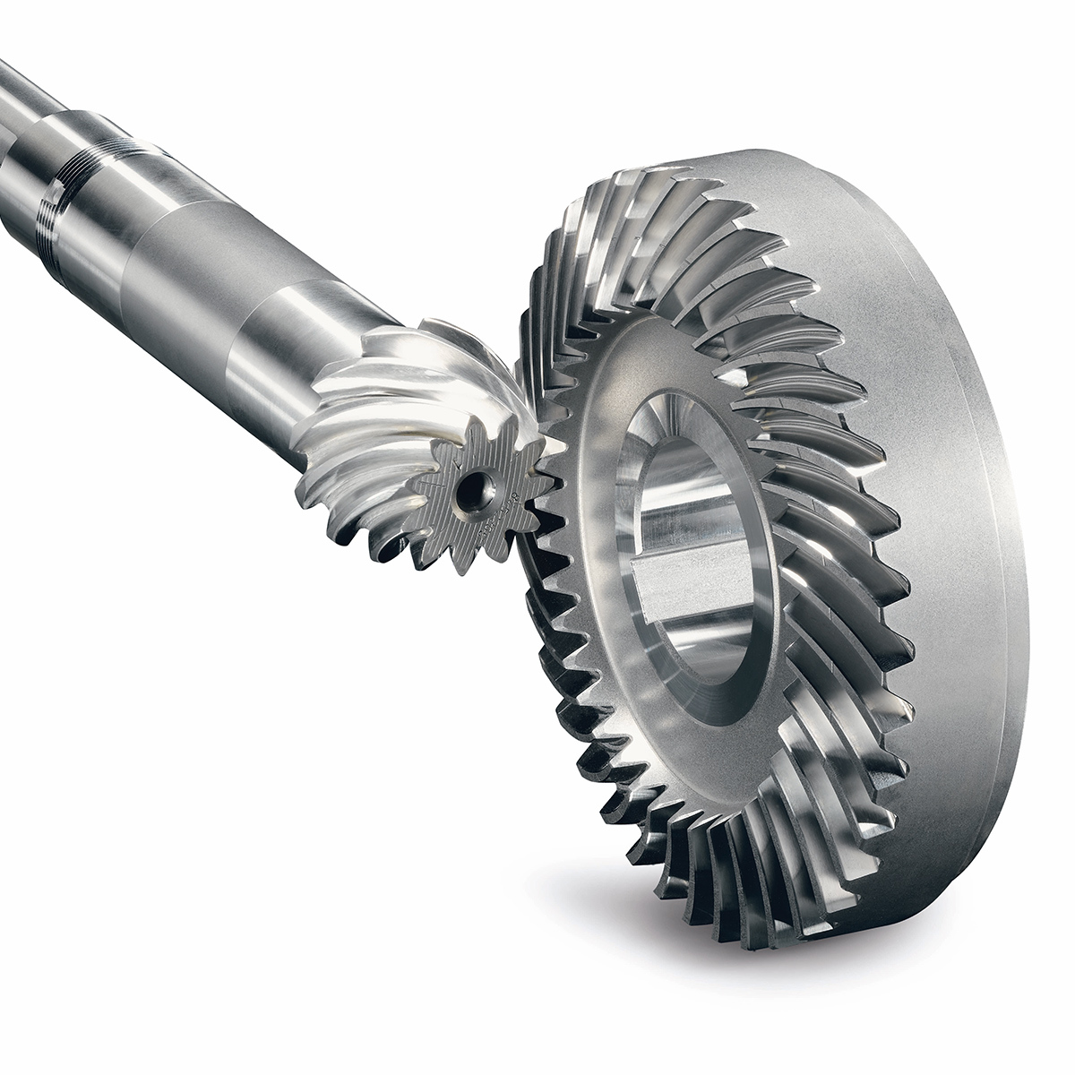
How do you install a bevel gear system?
Installing a bevel gear system involves several steps to ensure proper alignment, smooth operation, and efficient power transmission. Here’s a detailed explanation of how to install a bevel gear system:
- Preparation: Before installing the bevel gear system, gather all the necessary tools and equipment. Ensure that you have the correct bevel gears, shafts, bearings, and any additional components required for your specific application. Familiarize yourself with the system’s design, specifications, and installation instructions provided by the gear manufacturer.
- Clean and Inspect: Thoroughly clean all the components of the bevel gear system, including the gears, shafts, and bearings. Inspect them for any signs of damage, wear, or defects. Replace any damaged or worn-out parts to ensure optimal performance and longevity.
- Shaft Alignment: Proper alignment of the shafts is crucial for the bevel gear system’s performance. Ensure that the shafts are aligned accurately, both angularly and axially, as specified by the manufacturer. Misalignment can lead to premature wear, increased noise, and reduced efficiency. Use precision measurement tools, such as dial indicators, to achieve the required alignment.
- Bearing Installation: Install the bearings on the shafts according to the manufacturer’s instructions. Ensure that the bearings are securely fitted and properly lubricated. Proper bearing installation helps support the shafts, reduces friction, and ensures smooth rotation of the gears.
- Gear Meshing: Carefully position the bevel gears on the shafts, ensuring proper meshing between the teeth. The gear teeth should engage smoothly and evenly without any binding or excessive clearance. Achieving the correct gear meshing is crucial for efficient power transmission and to prevent premature wear or damage to the gears.
- Housing Assembly: Assemble the housing or casing that encloses the bevel gear system. Ensure that all housing components are aligned and securely fastened. Follow the manufacturer’s instructions for proper housing assembly, including the use of gaskets or seals to prevent lubricant leakage and contamination.
- Lubrication: Proper lubrication is essential for the smooth operation and longevity of the bevel gear system. Apply the recommended lubricant to the gears, bearings, and other moving parts according to the manufacturer’s specifications. Ensure that the lubricant used is compatible with the gear material, operating conditions, and environmental factors.
- Testing and Adjustment: After the installation is complete, perform a thorough system check. Rotate the shafts manually or using a suitable drive mechanism to ensure smooth gear operation, proper alignment, and absence of abnormal noise or vibration. Make any necessary adjustments, such as gear backlash or meshing depth, as per the manufacturer’s guidelines and based on the specific application requirements.
It’s important to note that the installation process may vary depending on the specific bevel gear system and application. Always refer to the manufacturer’s instructions and guidelines for the particular gear system you are working with to ensure proper installation and optimal performance.
In summary, installing a bevel gear system involves preparation, cleaning and inspection, shaft alignment, bearing installation, gear meshing, housing assembly, lubrication, and thorough testing and adjustment. Following proper installation procedures and adhering to manufacturer guidelines are essential to achieve efficient power transmission, smooth operation, and the desired performance from the bevel gear system.
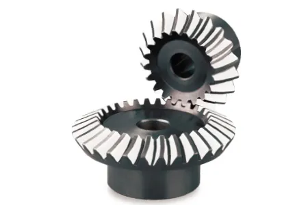
Come si assicura il corretto allineamento quando si collega una coppia conica?
Un allineamento corretto è fondamentale quando si collega un ingranaggio conico per garantire una trasmissione efficiente della potenza, un funzionamento regolare e una lunga durata del sistema di ingranaggi. Ecco una spiegazione dettagliata di come garantire un allineamento corretto:
Quando si collega un ingranaggio conico, le seguenti operazioni possono contribuire a garantire un allineamento corretto:
- Controllare le specifiche dell'ingranaggio: Per prima cosa, esaminare le specifiche dell'ingranaggio fornite dal produttore. Queste includono informazioni sul progetto dell'ingranaggio, sulle tolleranze e sui requisiti di allineamento. La comprensione di queste specifiche è essenziale per ottenere l'allineamento desiderato.
- Preparare le superfici di montaggio: Assicurarsi che le superfici di montaggio degli ingranaggi, come gli alberi o i riduttori, siano pulite, prive di detriti e adeguatamente preparate. Eventuali irregolarità o difetti superficiali possono influire sull'allineamento e causare problemi di disallineamento. Rimuovere eventuali bave, intaccature o punti ruvidi che potrebbero interferire con il corretto alloggiamento degli ingranaggi.
- Utilizzare gli strumenti di allineamento: Gli strumenti di allineamento, come gli indicatori a quadrante o i sistemi di allineamento laser, possono essere utili per ottenere un allineamento preciso. Questi strumenti consentono di misurare e regolare con precisione la posizione dell'ingranaggio rispetto ai componenti di accoppiamento. Seguire le istruzioni fornite con gli strumenti di allineamento per impostare ed eseguire correttamente il processo di allineamento.
- Allineamento assiale: Il corretto allineamento assiale è fondamentale per le ruote coniche. L'allineamento assiale si riferisce all'allineamento dell'asse di rotazione dell'ingranaggio parallelo all'asse di rotazione dell'ingranaggio di accoppiamento. Ciò garantisce un corretto ingranamento e una corretta distribuzione del carico. Utilizzare gli strumenti di allineamento per misurare e regolare l'allineamento assiale, apportando le necessarie modifiche alla posizione dell'ingranaggio o spessorando come richiesto.
- Allineamento radiale: L'allineamento radiale prevede l'allineamento dell'asse di rotazione dell'ingranaggio perpendicolare all'asse di rotazione dell'ingranaggio di accoppiamento. Un corretto allineamento radiale aiuta a prevenire i carichi laterali, l'usura eccessiva e la generazione di rumore. Utilizzare gli strumenti di allineamento per misurare e regolare l'allineamento radiale, assicurandosi che la posizione dell'ingranaggio sia regolata o spessorata correttamente per ottenere l'allineamento desiderato.
- Verificare lo schema di contatto dei denti: Dopo aver allineato gli ingranaggi, è importante verificare l'andamento del contatto dei denti. Lo schema di contatto dei denti deve essere uniformemente distribuito sulle superfici dei denti dell'ingranaggio per garantire una corretta ripartizione del carico e ridurre al minimo l'usura. Eseguire un'ispezione visiva o utilizzare strumenti specializzati, come i composti per la marcatura degli ingranaggi, per controllare e regolare lo schema di contatto dei denti, se necessario.
Seguendo questi passaggi e utilizzando gli strumenti di allineamento appropriati, è possibile garantire un allineamento corretto quando si collega una coppia conica. Un allineamento corretto favorisce una trasmissione efficiente della potenza, minimizza l'usura, riduce la rumorosità e prolunga la durata del sistema di ingranaggi.
Vale la pena di notare che ogni sistema di ingranaggi può avere requisiti e considerazioni specifiche per l'allineamento. Consultare le linee guida e le best practice del produttore di ingranaggi e rivolgersi a ingegneri esperti per garantire il corretto allineamento degli ingranaggi conici nella propria applicazione specifica.
What is a bevel gear and how does it work?
A bevel gear is a type of gear that has teeth cut on the cone-shaped surface of the gear. It is used to transmit rotational motion and power between two intersecting shafts. Here’s a detailed explanation of what a bevel gear is and how it works:
A bevel gear consists of two cone-shaped gears with intersecting axes. The gear teeth are cut on the tapered surface of the gears. The gear with the smaller diameter is called the pinion, while the gear with the larger diameter is called the crown gear or ring gear.
Bevel gears are classified into different types based on their tooth geometry and arrangement. The most common types are straight bevel gears, spiral bevel gears, and hypoid bevel gears. Straight bevel gears have straight-cut teeth and intersect at a 90-degree angle. Spiral bevel gears have curved teeth that are gradually cut along the gear surface, allowing for smoother engagement and reduced noise. Hypoid bevel gears have offset axes and are used when the intersecting shafts are non-parallel.
When two bevel gears mesh together, the rotational motion from one gear is transmitted to the other gear. The gear teeth engage and disengage as the gears rotate, transferring torque and power between the shafts.
The operation of bevel gears is similar to that of other types of gears. When the pinion gear rotates, it causes the crown gear to rotate in the opposite direction. The direction of rotation can be reversed by changing the orientation of the gears. Bevel gears can provide different speed ratios and torque conversions depending on the gear sizes and the number of teeth.
The key characteristics of bevel gears include:
- Transmission of motion: Bevel gears are used to transmit rotational motion between intersecting shafts, allowing for changes in direction and speed.
- Torque transfer: Bevel gears can transmit torque from one shaft to another, allowing for power transmission in various mechanical systems.
- Axial thrust: Due to the angled tooth arrangement, bevel gears generate axial thrust forces that need to be properly supported or accounted for in the design of the mechanical system.
- Efficiency and noise: The efficiency and noise characteristics of bevel gears depend on factors such as tooth design, lubrication, and manufacturing quality.
Bevel gears are commonly used in a wide range of applications, including automotive differentials, power tools, printing presses, machine tools, and marine propulsion systems. Their ability to transmit motion and torque at intersecting angles makes them versatile and suitable for various mechanical systems.
In summary, a bevel gear is a cone-shaped gear that transmits rotational motion and power between intersecting shafts. It works by meshing the gear teeth of two gears, allowing for the transfer of torque and rotational motion. Bevel gears are available in different types and are used in various applications that require changes in direction or speed of rotational motion.


editor by Dream 2024-05-15
 Italian
  English