
Descrizione del prodotto
Straight Teethed Bevel Gear/ High Efficiency Gear/ Straight Bevel Gear
1.Description
| No. | Item | Description |
| 1 | Name | Straight Bevel Gear |
| 2 | Size | Products can be customized. |
| 3 | Material | 45#Steel,20CrMnTi,40Cr,20CrNiMo,20MnCr5,GCR15SiMn,42CrMo,2Cr13stainless steel,Nylon,Bakelite,Copper,Aluminium.etc |
| 4 | Production Process | The main process is Gear Milling and Gear Shaping, Selecting production process according to the different products. |
| 5 | Heat Treatment | Carburizing and quenching ,High-frequency quenching,Nitriding, Hardening and tempering, Selecting heat treatment according to the different materials. |
| 6 | Testing Equipment | Rockwell hardness tester 500RA, Double mesh instrument HD-200B & 3102,Gear measurement center instrument CNC3906T and other High precision detection equipments |
| 7 | Certification | GB/T19001-2016/ISO9001:2015 |
| 8 | Usage | Used in printing machine, cleaning machine, medical equipment, garden machine, construction machine, electric car, valve, forklift, transportation equipment and various gear reducers.etc |
| 9 | Package | According to customer’s request |
2. Photos
Order process
a. You seng us drawing or sample.
b. We process scheme and quotation for your products.
c. We make the sample and send it to you after you confirmed our design.
d. You confirm the sample then place an order and pay us 50% deposit.
e. We start producing.
f.When the goods is done, you pay us the balance after you confirmed pictures or tracking numbers.
g.Trade is done, thank you!
| Applicazione: | Electric Cars, Machinery, Agricultural Machinery, Industry |
|---|---|
| Hardness: | Hardened |
| Gear Position: | Ingranaggio conico |
| Manufacturing Method: | Gear Grinding |
| Forma della porzione dentata: | Involute |
| Materiale: | 45#Steel,20crmnti,40cr,20CrNiMo,20mncr5,Gcr15simn, |
| Samples: |
US$ 15/Piece
1 Piece(Min.Order) | |
|---|
| Customization: |
Available
| Customized Request |
|---|
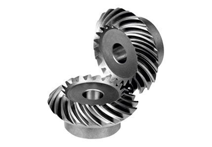
How do you prevent backlash and gear play in a bevel gear mechanism?
In a bevel gear mechanism, preventing backlash and gear play is essential for ensuring accurate and efficient power transmission. Backlash refers to the clearance or free movement between the mating teeth of gears, resulting in a brief loss of motion or a dead zone when changing direction. Here are some methods to prevent backlash and minimize gear play in a bevel gear mechanism:
- Precision Manufacturing: High-precision manufacturing processes are crucial for minimizing backlash and gear play in bevel gears. Accurate machining of gear teeth and precise control of tooth dimensions, profiles, and alignment help achieve tight meshing between the gears, reducing the clearance and backlash. Modern manufacturing techniques, such as CNC machining and gear grinding, can ensure the desired level of precision and minimize gear play.
- Proper Gear Design: The design of the bevel gears can influence the amount of backlash and gear play. An optimized gear design, including suitable tooth profiles, pressure angles, and tooth contact patterns, can help distribute the load evenly and minimize the clearance between the mating teeth. By carefully considering gear design parameters, designers can reduce backlash and improve gear meshing characteristics.
- Preload or Pre-Tension: Applying a preload or pre-tension to the bevel gears can help minimize backlash and gear play. This involves applying a slight force or tension to the gears, forcing them to maintain contact and reducing the clearance between the teeth. Preload can be achieved through various methods, such as using spring mechanisms, shimming, or adjusting the mounting position of the gears.
- Backlash Compensation: Backlash compensation methods aim to minimize the effects of backlash and gear play by introducing mechanisms or techniques that compensate for the clearance. One common approach is to use anti-backlash gears, which have special tooth profiles or arrangements that reduce or eliminate clearance between the mating teeth. Another method is to incorporate backlash compensation devices, such as spring-loaded mechanisms or adjustable shims, that actively reduce the backlash during operation.
- Tight Control of Tolerances: Maintaining tight tolerances during the manufacturing and assembly processes is critical for minimizing backlash and gear play. Close control of dimensions, alignment, and clearances ensures proper gear meshing and reduces the possibility of excessive play. Quality control measures, such as inspection, testing, and verification of gear dimensions, can help ensure that the gears meet the specified tolerances.
- Regular Maintenance: Regular maintenance practices, including inspection, lubrication, and adjustment, are essential for preventing and minimizing backlash and gear play over time. Periodic checks for wear, misalignment, and proper lubrication can help identify and rectify any issues that may contribute to increased backlash. Timely maintenance and replacement of worn or damaged gears can help maintain optimal gear meshing and minimize play.
By implementing these methods, it is possible to significantly reduce backlash and gear play in a bevel gear mechanism, resulting in improved accuracy, efficiency, and longevity of the gear system.
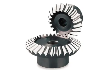
Come si assicura il corretto allineamento quando si collega una coppia conica?
Un allineamento corretto è fondamentale quando si collega un ingranaggio conico per garantire una trasmissione efficiente della potenza, un funzionamento regolare e una lunga durata del sistema di ingranaggi. Ecco una spiegazione dettagliata di come garantire un allineamento corretto:
Quando si collega un ingranaggio conico, le seguenti operazioni possono contribuire a garantire un allineamento corretto:
- Controllare le specifiche dell'ingranaggio: Per prima cosa, esaminare le specifiche dell'ingranaggio fornite dal produttore. Queste includono informazioni sul progetto dell'ingranaggio, sulle tolleranze e sui requisiti di allineamento. La comprensione di queste specifiche è essenziale per ottenere l'allineamento desiderato.
- Preparare le superfici di montaggio: Assicurarsi che le superfici di montaggio degli ingranaggi, come gli alberi o i riduttori, siano pulite, prive di detriti e adeguatamente preparate. Eventuali irregolarità o difetti superficiali possono influire sull'allineamento e causare problemi di disallineamento. Rimuovere eventuali bave, intaccature o punti ruvidi che potrebbero interferire con il corretto alloggiamento degli ingranaggi.
- Utilizzare gli strumenti di allineamento: Gli strumenti di allineamento, come gli indicatori a quadrante o i sistemi di allineamento laser, possono essere utili per ottenere un allineamento preciso. Questi strumenti consentono di misurare e regolare con precisione la posizione dell'ingranaggio rispetto ai componenti di accoppiamento. Seguire le istruzioni fornite con gli strumenti di allineamento per impostare ed eseguire correttamente il processo di allineamento.
- Allineamento assiale: Il corretto allineamento assiale è fondamentale per le ruote coniche. L'allineamento assiale si riferisce all'allineamento dell'asse di rotazione dell'ingranaggio parallelo all'asse di rotazione dell'ingranaggio di accoppiamento. Ciò garantisce un corretto ingranamento e una corretta distribuzione del carico. Utilizzare gli strumenti di allineamento per misurare e regolare l'allineamento assiale, apportando le necessarie modifiche alla posizione dell'ingranaggio o spessorando come richiesto.
- Allineamento radiale: L'allineamento radiale prevede l'allineamento dell'asse di rotazione dell'ingranaggio perpendicolare all'asse di rotazione dell'ingranaggio di accoppiamento. Un corretto allineamento radiale aiuta a prevenire i carichi laterali, l'usura eccessiva e la generazione di rumore. Utilizzare gli strumenti di allineamento per misurare e regolare l'allineamento radiale, assicurandosi che la posizione dell'ingranaggio sia regolata o spessorata correttamente per ottenere l'allineamento desiderato.
- Verificare lo schema di contatto dei denti: Dopo aver allineato gli ingranaggi, è importante verificare l'andamento del contatto dei denti. Lo schema di contatto dei denti deve essere uniformemente distribuito sulle superfici dei denti dell'ingranaggio per garantire una corretta ripartizione del carico e ridurre al minimo l'usura. Eseguire un'ispezione visiva o utilizzare strumenti specializzati, come i composti per la marcatura degli ingranaggi, per controllare e regolare lo schema di contatto dei denti, se necessario.
Seguendo questi passaggi e utilizzando gli strumenti di allineamento appropriati, è possibile garantire un allineamento corretto quando si collega una coppia conica. Un allineamento corretto favorisce una trasmissione efficiente della potenza, minimizza l'usura, riduce la rumorosità e prolunga la durata del sistema di ingranaggi.
Vale la pena di notare che ogni sistema di ingranaggi può avere requisiti e considerazioni specifiche per l'allineamento. Consultare le linee guida e le best practice del produttore di ingranaggi e rivolgersi a ingegneri esperti per garantire il corretto allineamento degli ingranaggi conici nella propria applicazione specifica.
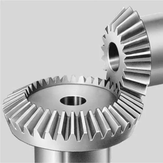
How do you calculate the gear ratio of a bevel gear?
Calculating the gear ratio of a bevel gear involves determining the ratio between the number of teeth on the driving gear (pinion) and the driven gear (crown gear). Here’s a detailed explanation of how to calculate the gear ratio of a bevel gear:
The gear ratio is determined by the relationship between the number of teeth on the pinion and the crown gear. The gear ratio is defined as the ratio of the number of teeth on the driven gear (crown gear) to the number of teeth on the driving gear (pinion). It can be calculated using the following formula:
Gear Ratio = Number of Teeth on Crown Gear / Number of Teeth on Pinion Gear
For example, let’s consider a bevel gear system with a crown gear that has 40 teeth and a pinion gear with 10 teeth. The gear ratio can be calculated as follows:
Gear Ratio = 40 / 10 = 4
In this example, the gear ratio is 4:1, which means that for every four revolutions of the driving gear (pinion), the driven gear (crown gear) completes one revolution.
It’s important to note that the gear ratio can also be expressed as a decimal or a percentage. For the example above, the gear ratio can be expressed as 4 or 400%.
Calculating the gear ratio is essential for understanding the speed relationship and torque transmission between the driving and driven gears in a bevel gear system. The gear ratio determines the relative rotational speed and torque amplification or reduction between the gears.
It’s worth mentioning that the gear ratio calculation assumes ideal geometries and does not consider factors such as backlash, efficiency losses, or any other system-specific considerations. In practical applications, it’s advisable to consider these factors and consult gear manufacturers or engineers for more accurate calculations and gear selection.
In summary, the gear ratio of a bevel gear is determined by dividing the number of teeth on the crown gear by the number of teeth on the pinion gear. The gear ratio defines the speed and torque relationship between the driving and driven gears in a bevel gear system.


editor by CX 2023-10-07
 Italian
  English